ROCKWELL HARDNESS
Indenters and Rockwell scales
There are several types of indenters. Consisting of a diamond cone or a tungsten carbide ball of different sizes, these different indenters give access to different Rockwell hardness scales (HR from A to G, the HRC scale, applicable to steel, cast iron and titanium, is the most common one).
The principle of Rockwell tests
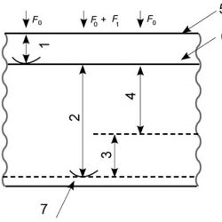
In order to obtain a Rockwell hardness value, a pre-load force (F0) is applied, which deforms the material. This position is the origin of the test. The Hardness Tester then applies the test load (F0 + F1) which continues the deformation of the material and then returns to the pre-load force (F0). The measured hardness is directly related to the depth of the ‘h’ tests in the following diagram weighted by a unit-specific factor (S) and a constant
HRX = C – h/S.
(C takes the value 130 for the HR B, E F, G, H K scale and 100 for the A, C, D, N and T scales)
S takes the value 0.001 for the N and T scales and 0.002 for all other ones.
A Rockwell hardness unit consists of a residual depth corresponding to the S value in mm.

2 Indentation depth by additional test force F1
3 Elastic recovery just after removal of additional test force F1
4 Permanent indentation depth h
5 Surface of specimen
6 Reference plane for measurement
7 Position of indenter
A distinction exists between Rockwell hardness tests and superficial Rockwell tests, which are applicable to coatings, to thin samples; these are the N and T scales.
The difference between the two types of tests lies in the loads and pre-loads used (lower in the case of the superficial Rockwell tests). A superficial Rockwell hardness unit corresponds to a residual depth of 1 μm (0.001 mm).

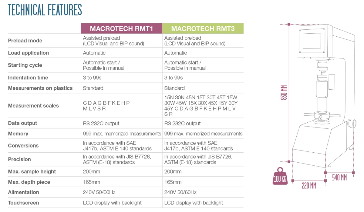
TABLE RMT1-RMT3

